Once object description has been transmitted to the viewing reference frame, we choose the window extends in viewing coordinates and selects the viewport limits in normalized coordinates.
Object descriptions are then transferred to normalized device coordinates:
We do this thing using a transformation that maintains the same relative placement of an object in normalized space as they had in viewing coordinates.
If a coordinate position is at the center of the viewing window:
It will display at the center of the viewport.
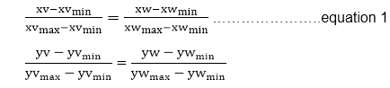
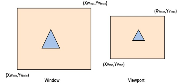
Fig shows the window to viewport mapping. A point at position (xw, yw) in window mapped into position (xv, yv) in the associated viewport.
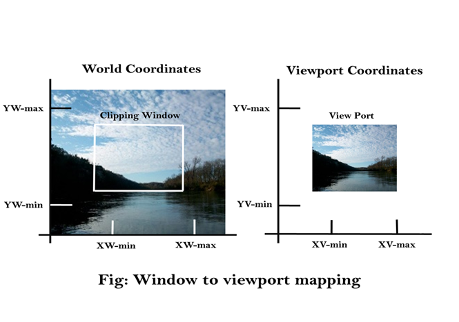
In order to maintain the same relative placement of the point in the viewport as in the window, we require:
Solving these impressions for the viewport position (xv, yv), we have
xv=xvmin+(xw-xwmin)sx
yv=yvmin+(yw-ywmin)sy ...........equation 2
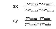
Where scaling factors are
Equation (1) and Equation (2) can also be derived with a set of transformation that converts the window or world coordinate area into the viewport or screen coordinate area. This conversation is performed with the following sequence of transformations:
- Perform a scaling transformation using a fixed point position (xwmin,ywmin) that scales the window area to the size of the viewport.
- Translate the scaled window area to the position of the viewport. Relative proportions of objects are maintained if the scaling factors are the same (sx=sy).
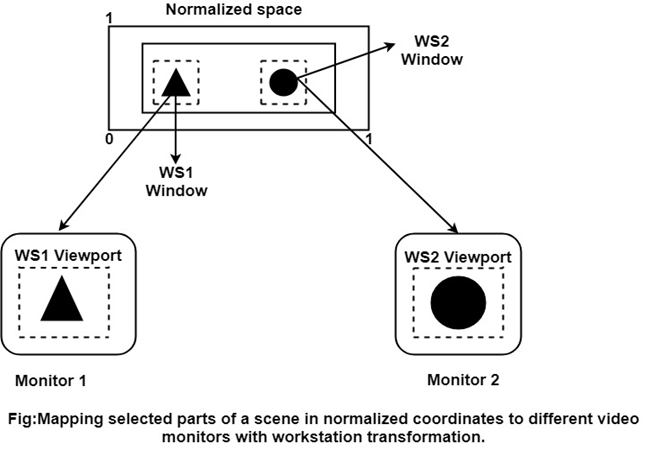
From normalized coordinates, object descriptions are mapped to the various display devices.
Any number of output devices can we open in a particular app, and three windows to viewport transformation can be performed for each open output device.
This mapping called workstation transformation (It is accomplished by selecting a window area in normalized space and a viewport area in the coordinates of the display device).
As in fig, workstation transformation to partition a view so that different parts of normalized space can be displayed on various output devices).
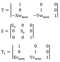
Matrix Representation of the above three steps of Transformation:
Step1:Translate window to origin 1
Tx=-Xwmin Ty=-Ywmin
Step2:Scaling of the window to match its size to the viewport
Sx=(Xymax-Xvmin)/(Xwmax-Xwmin)
Sy=(Yvmax-Yvmin)/(Ywmax-Ywmin)
Step3:Again translate viewport to its correct position on screen.
Tx=Xvmin
Ty=Yvmin
Above three steps can be represented in matrix form:
VT=T * S * T1
T = Translate window to the origin
S=Scaling of the window to viewport size
T1=Translating viewport on screen.
Viewing Transformation= T * S * T1
Advantage of Viewing Transformation:
We can display picture at device or display system according to our need and choice.
Note:
- World coordinate system is selected suits according to the application program.
- Screen coordinate system is chosen according to the need of design.
- Viewing transformation is selected as a bridge between the world and screen coordinate.