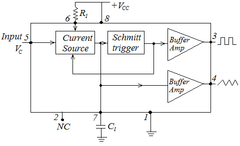
The block diagram of voltage control oscillator is given in fig. 9. In most the cases, the frequency of an oscillation is determined by the time constant RC. However, in cases or applications such as FM., tone generation, and frequency shifting keying (FSK), the frequency is to be controlled by means of an input voltage, called the control voltage. This can be achieved in a voltage controlled oscillator (VCO). A voltage controller oscillator is a circuit that provides an oscillating output signal whose frequency can be adjusted over a range by a dc voltage. The frequency of oscillation is set by an external resistor R1 and a capacitor C1 and the voltage Vc applied to the control terminal. The current source block is used to charging and discharging the capacitor C1, at a rate set by an external resistor R1, and the modulating dc input voltage. A Schmitt trigger circuit is employed to switch the current sources between charging and discharging the capacitor, and the triangular voltage produced across the capacitor and square wave from the Schmitt trigger are provided as outputs through buffer amplifier.
The frequency of oscillation at the output waveform is approximately
\(f_{out}=\frac{2\left(V_{CC}-V_C\right)}{R_1C_1V_{CC}}\)

Fig. 9 Block diagram of VCO
Applications:
The voltage control oscillators (VCO) are commonly used in converting low frequency signal such as EEG (electro - encephalograms) or ECG (electro - cardiograms) into an audio frequency. The VCO can be programmed over a 10 – 1 frequency range by proper selection of an external resistor and capacitor.
