In general , the resonance means a particular situation in a physical system where a sinusoidal force having a constant amplitude gives rise to an enhanced response of maximum amplitude varying with time. When resonance occur an exchange of energy takes place between the forcing system and the source.
Expression of frequency in a series RLC circuit at resonance:

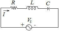
Fig. 3 Series RLC circuit
The series RLC circuit is given in Fig. 3. The designed circuit consists of resistance R, inductance L and capacitance C in series configuration. Let us consider the current I flowing through the series RLC circuit by the a.c. voltage source with constant value of \(V_S\). The complex impedance in the circuit is given by
\(Z=R+j\omega L+\frac{1}{j\omega c}=R+j(\omega L-\frac{1}{\omega C})\)
The current in the circuit
\(I=\frac{V_S}{Z}=\frac{V_S}{R+j(\omega L-\frac{1}{\omega C})}\)
The magnitude of impedance of inductive and capacitive are \(X_L=\omega L\) and \(X_C=\frac{1}{\omega C}\)
The magnitude of impedance
\(\left|Z\right|=\sqrt{R^2+\left(X_L+X_C\right)^2}\)
It can be easily seen from above the expressions that the inductive impedance value is increase linearly with the frequency and capacitive impedance \(X_C\) decreases with the increase of frequency. The resistance R does not depend on the frequency. At a certain frequency current flowing through the RLC series circuit is maximum and in – phase with the applied voltage and the circuit behaves like a resistive circuit and series resonance is obtained. At the series resonance, inductive and capacitive impedance numerical values are same. Therefore we can write
\(X_L=X_C\)
At \(\omega=\omega_0\), we have,
\(\omega_0L=\frac{1}{\omega_0C}\)
\(2\pi f_0L=\frac{1}{2\pi f_0C}\)
Hence the resonance frequency of series RLC circuit is given by:––
\(f_0=\frac{1}{2\pi\sqrt{LC}}\)
Expression of frequency in a parallel RLC circuit at resonance:
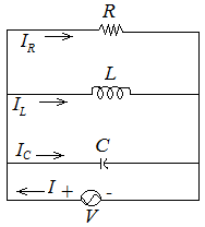
 Fig.26
According to the Fig. (a), we have
\(I=I_R+I_L+I_C\)
Or \(I=\frac{V}{R}-j\frac{V}{\omega L}+jV\omega C\)
Or \(I=V\left[\frac{1}{R}+j(\omega C-\frac{1}{\omega L})\right]\)
\(I=V\left[\frac{1}{R}+j\left(\frac{1}{X_C}-\frac{1}{X_L}\ \right)\right]=\frac{V}{Z}=VY\)
Therefore the complex admittance \(Y=\frac{1}{Z}=\frac{1}{R}+j(\omega C-\frac{1}{\omega L})\).
The complex impedance \(Z=\frac{1}{Y}=\frac{1}{\frac{1}{R}+j(\omega C-\frac{1}{\omega L})}\)
If the conductance and susceptance be G and B respectively
Thus \(Y=G+jB=\frac{1}{R}+j(\omega C-\frac{1}{\omega L})\)
\(G=\frac{1}{R},\ B=\omega C-\frac{1}{\omega L}=B_C-B_L\)
At the resonance \(B_C=B_L\)
\(\omega C=\frac{1}{\omega L}\)
\(\omega^2=\frac{1}{LC}\)
The resonance frequency of parallel RLC circuit is \(f_0=\frac{1}{2\pi\sqrt{LC}}\)

 Fig.23