FM stereo transmitter and receiver system
A stereo FM transmission is a system in which, adequate information is sent to the receiver in order to reproduce the original stereo sound signal. The stereo FM system is made compatible with the usual mono FM system, so that it is possible to receive FM stereo transmission even using mono FM receiver. The block diagram of stereo FM multiplexing generator is given in Fig. 37.
Working principle:
The two input channels are passed through a matrix which produces two outputs namely (L+R) the sum component and (L-R), the difference component. The sum component is modulated by the frequency modulator. A sub carrier signal with 19 KHz is multiply with frequency multiplier and it is doubled by the frequency doublers circuit. The 38 KHz frequency band and difference component of (L-R) is passed through balanced modulator circuit. The output of the balanced modulator signal is combined with the sum signal, 19 KHz frequency signal and the output of the SCA generator. The combined signal is modulated by the frequency modulator.

Fig. 37 FM stereo transmitter block diagram with optical SCA
Receiver:
The output signal of the transmitter is first amplified using a wideband amplifier. The LPF remove all the frequency above 15 KHz to produces an (L+R) signal at its output. A band pass filter (BPF) is used to selecting two side bands of (L-R) signal. The frequency band of two side frequency bands are 23 KHz to 53 KHz. These side frequency bands are applied to the single side band (SSB) demodulator to modulate the signal. The used carrier frequency of this SSB demodulator is 38 KHz. The output of the demodulator is (L-R) signal with frequency band 50 Hz to 15 KHz. The adder / subtractor matrix, produces the left channel by adding the (L+R) and (L-R) signal. The SCA signal is selected using an SCA trap, demodulated using an FM demodulator, de- emphasized to produce a separate audio output.
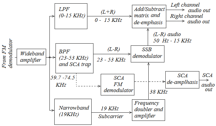 Fig.38 FM stereo receiver block diagram