For measurement of capacitance and dissipation factor Schering bridge is widely used. The phasor diagram and circuit diagram of the bridge are as follows:
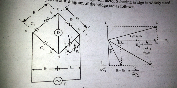
Let, \(C_1\) = Capacitor of unknown capacitance.
\(R_1\) = a series resistance representing the loss in capacitor \(C_1\).
\(C_2\) = a standard capacitor
\(R_3\) = a non-inductive resistance
\(C_4\) = a variable capacitor
\(R_4\) = a variable non-inductive resistance in parallel with \(C_4\).
At balance,
\(\left(r_1+\frac{1}{j\omega C_1}\right)\left(\frac{R_4}{1+j\omega C R_4}\right)=\frac{1}{j\omega C_2}.R_3\)
\(\left(r_1+\frac{1}{j\omega C_1}\right)R_4=\frac{R_3}{j\omega C_2}\left(1+j\omega C_4R_4\right)\)
\(r_1R_4-\frac{jR_4}{\omega C_1}=j\frac{R_3}{\omega C_2}+\frac{R_3R_4C_4}{C_2}\)
Equating imaginary and real parts,
\(r_1R_4=\frac{R_3R_4C_4}{C_2}\ \ \ \ \ \ \ \ \ \ \ \ \ \ \ \ \ \ \ \ \ \ \ \ \ \ \ \therefore r_1=\frac{R_3C_4}{C_2}\)
and, \(-\frac{jR_4}{\omega C_1}=-j\frac{R_3}{\omega C_2}\ \ \ \ \ \ \ \ \ \ \ \ \ \ \ \ \ \ \ \ \ \ \ \ \therefore\ C_1=\frac{R_4}{R_3}C_2\)
Dissipation factor \(D_1=tan\delta=\omega C_1r_1\)