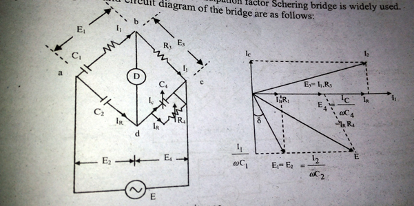
For measurement of capacitance and dissipation factor Schering bridge is widely used. The phasor diagram and circuit diagram of the bridge are as follows:
Let,
At balance,
Equating imaginary and real parts,
and,
Dissipation factor
Describe the process of capacitance measurement using De Sauty’s bridge and draw the relevant phasor diagram. State the limitations of the bridge.
For measurement of capacitance and dissipation factor Schering bridge is widely used. The phasor diagram and circuit diagram of the bridge are as follows:
Let,
At balance,
Equating imaginary and real parts,
and,
Dissipation factor
MindStudy - a preparation hub for all the students. The goal is to make it easier for pupils to get better grades on exams.
Copyright © 2025 MindStudy
A product by Shunya Intelliware Solution
(Registered under MSME Uddyam)