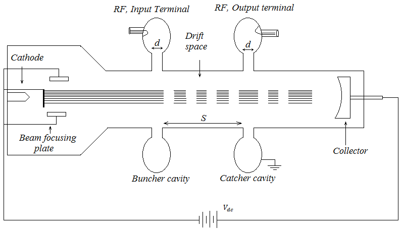
 Fig. 31 Two cavity Klystron.
The Klystron tube operates on the principle of velocity modulation instead of current density modulation employed in conventional tubes. The idea of Klystron Amplifier was introduced by Varian brothers in 1939. The typical diagram of two cavity Klystron amplifier is depicted in Fig. 31. It consists of electron gun, buncher cavity, catcher cavity and collector. Electrons emitted by the cathode are focused by one or more focusing electrodes kept in front of the cathode. The electron beam then passes through buncher and catcher cavity and finally collected by the collector. With the help of coupling loop the electromagnetic power or RF power can be coupled through the buncher and catcher cavity.
The electric field component in the cavity is collinear with the beam axis. The electron beam when passes through the buncher cavity will see a varying accelerating field from positive to negative through zero. Thus the electrons passing through the first cavity when the voltage across the gap is zero continue with unchanged velocity along the drift space towards the catcher, this electron can be called reference electro. An electron passing through the same cavity slightly later in time is accelerated by the positive field at the gap. This electron speeds up and tends to overtake the reference electron ahead of it in the drift space. However an electron the passes through the cavity slightly before the reference electron encounter a negative field and is slow down. This electron tends to fall back towards the following reference electro. This phenomenon is known as velocity modulation and whose mathematical support is given below
\(v_1=v_0\left(1+\frac{V_1}{2V_{dc}}\sin{\omega t_1}\right)\)
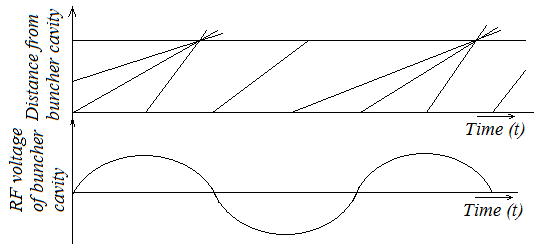
Thus as a result of passing the alternating field of the input buncher cavity, the electrons gradually bunch together as they travel down the drift space. The bunching effect converts the velocity modulation into density modulation of the beam. Now bunched electrons passing through catcher cavity induced current pulses in the cavity. Thus transferring energy to the catcher cavity, the electron beam finally reaches the collector with reduced velocity.
 Fig. 32 Applegate diagram for Klystron Amplifier
Reflex Klystron:
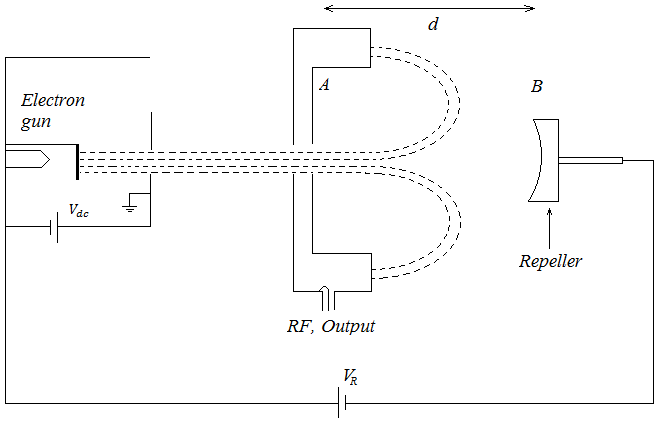
Reflex Klystron consists an electron gun producing a collimated beam of electron, which when passes through resonator cavity gets accelerated under a d.c accelerating voltage Vdc. The D.C. velocity of electrons in the beam will be,
\(v_o=\sqrt{\frac{2eV_{dc}}{m}}\)
Where e and m are the electron charge and mass respectively. The repeller which is placed very close to catcher cavity is kept at a negative potential VR with respect to cathode and consequently it retards and finally reflected the electrons which then turn back through the resonator grid. The constructional details is shown in Fig. 33

Fig. 33 Reflex Klystron oscillator
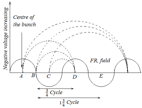
On passing through the cavity gap the electron beams get velocity modulated and get bunched in the drift space existing between cavity and repeller. The bunching process in a reflex Klystron oscillator is being described in Fig. 34 here the electrons with higher velocities will penetrate deeper in the drift region and will take more time to return to the cavity gap than the electrons with lower velocities, which penetrate shorter distance in the drift space. Thus the electrons leaving the gap at different instance returning back to the cavity at the same time resulting the desired bunching effect. When these bunching electrons will be repelled by the repeller plate, come back to the cavity and deliver power to it at an instant when the field retards the bunch, i.e. the peak value of R.F field. If this transferred energy is equal to or more than the losses take place in resonator, the oscillation occurs.

Fig. 34 Electron bunching phenomenon of Reflex Klystron
