A pure resistive circuit is shown in Fig. 12(a) contain a pure resistance R connected across an AC sinusoidal voltage source. The instantaneous value of an alternating source voltage is given by
\(v\left(t\right)=\ V_m\sin{\omega t}=I_m\left[V_me^{j\omega t}\right]\) …(1)
Where \(V_m\) is the peak voltage in volt. Here f is the frequency of alternating voltage. Instantaneous value of current i is obtained by using Ohm’s law.
Thus
\(i=\frac{v}{R}=\frac{V_m}{R}\sin{\omega t}\) … (2)
Alternatively
\(i=\frac{V_m}{R}\sin{\omega t}=I_m\left[\frac{V_m}{R}e^{j\omega t}\right]=I_m\left[I_me^{j\omega t}\right]\) … (3)
Where
\(I_m=\frac{V_m}{R}\)=peak value of current
Equation (1) and equation (2) indicate
That current and voltage across the circuit have sinusoidal waves hap with the same angular velocity \omega. Also current and voltage are in phase. The phasor diagram shown in Fig. 12(c) is drawn in terms of RMS values of voltage and current phasors where
\(V_{rms}=\frac{V_m}{\sqrt2} and I_{rms}=\frac{I_m}{\sqrt2}\)
If V=V<0
Then \(I=\frac{V}{R}<0\)
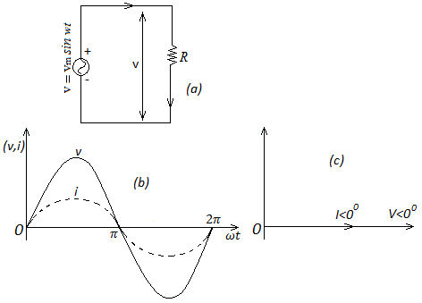 Fig.12(a) Pure resistive circuit diagram, (b) instantaneous voltage, current and voltage waveform and (c) phasor diagram
Pure capacitive circuit:
A pure capacitor has capacitance C farads only without having any resistance. Thus it is assume that current following through the capacitor causes no heating. In practical commercial capacitors, a very small amount of power loss takes place in the dielectric median in addition to negligible \(I^2R\) loss due to the flow of current in the capacitor place processing some resistance. The pure capacitive circuit shown in Fig. 13(a) consists of a pure capacitor having a capacitance of C farad connected cross an alternating sinusoidal voltage source.
The instantaneous value of the alternating voltage source is given by
\(V=V_msin\ \omega t=I_m\left[V_m\ e^{j\omega t}\right]\) …(1)
Where \(V_m\) is the maximum voltage and \(\omega=2\pi f\ rad/sec(f=50\ Hz)\)
If the charge on the capacitor at any instant of time t be q coulombs then the potential difference \(V_c\) across the plates of the capacitor is given by
\(V_c=\frac{q}{C}\)
In the steady state when all transient disappear, applying KVL around the closed circuit of Fig. 13(a)
\(v-V_c=0\)
Or \(v=V_c\)
Therefore
\(\frac{q}{v}=V_c=v=V_m\ sin\ \ \omega t\) …(2)
Or
\(q={C\ V}_m\ sin\ \ \omega t\) …(3)
The current flowing in the circuit is the rate of flow of charge and is given by
\(i=\frac{dq}{dt}=\frac{d}{dt}(CV_m\ sin\ \omega t)\)
Where the value of q is substituted from equation (3).
Thus
\(i=C\frac{d}{dt}\left(V_m\ sin\ \omega t\right)=\omega CV_mcos\ \omega t=\omega CV_m\ sin\ (\omega t+\frac{\pi}{2})\)
\(i=\frac{V_m}{1/\omega C}sin\ (\omega t+\frac{\pi}{2})\) … (4)
\(i=\frac{V_m}{X_C}sin\ (\omega t+\frac{\pi}{2})\) … (5)
\(i=I_msin\ (\omega t+\frac{\pi}{2})\) …(6)
Where \(I_m=\frac{V_m}{X_C}\) and \(X_C=1/\omega C\) is called capacitive reactance. The unit of \(X_C\) is ohm where \(\omega\) is in rad/sec and C is in farad. The usual convention is to use RMS values of current and voltage \((I_{rms},V_{rms})\) instead of their maximum values \((I_m,V_m)\)
\(I_{rms}=\frac{I_m}{\sqrt2}=\frac{V_m}{\sqrt2X_C}=\frac{V_{rms}}{X_C}\) …(7)
Equations (1) and (6) indicate that a sinusoidal alternating voltage applied to a pure capacitive circuit gives rise to a sinusoidal alternating current having the same angular frequency as that of applied voltage. However the peak value of current \(I_m\) is attained before a time \(\frac{\pi}{2\omega}\) second or phase angle \(\frac{\pi}{2}\) radian that the voltage has reached its peak value, \(V_m\). This is indicate in Fig. 13(b) where the voltage and current waveforms are shown. The phasor diagram of pure capacitive circuit shown in Fig. 13(c) indicates that the current phasor leads the voltage phasor by \(\frac{\pi}{2}radian\ or\ {90}^0\)
Thus
\(V=V_m<0\) …(8)
\(I=\frac{V_{rms}}{1/\omega C}<{90}^0\) …(9)
.png) Fig. 13(a)pure inductive circuit diagram, (b) instantaneous voltage, current and voltage waveform and (c) phasor diagram
Fig. 13(a)pure inductive circuit diagram, (b) instantaneous voltage, current and voltage waveform and (c) phasor diagram
 Fig.23